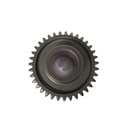
Designing a gear system is a complex yet rewarding process that requires a deep understanding of mechanical engineering principles, material properties, and application-specific requirements. As a seasoned gear supplier, I’ve had the privilege of working on numerous gear system design projects, from small-scale consumer products to large industrial machinery. In this blog, I’ll share my insights and experiences on how to design an effective gear system, covering everything from initial concept to final implementation. Gear
Understanding the Basics of Gear Systems
Before diving into the design process, it’s essential to have a solid understanding of the basic principles of gear systems. Gears are mechanical components with teeth that mesh together to transmit power and motion between rotating shafts. They come in various types, including spur gears, helical gears, bevel gears, and worm gears, each with its own unique characteristics and applications.
- Spur Gears: The simplest and most common type of gear, spur gears have straight teeth parallel to the axis of rotation. They are easy to manufacture and are suitable for applications where high speeds and low to moderate loads are required.
- Helical Gears: Helical gears have teeth that are cut at an angle to the axis of rotation, which allows for smoother and quieter operation compared to spur gears. They can transmit higher loads and are often used in applications where high efficiency and precision are required.
- Bevel Gears: Bevel gears are used to transmit power between intersecting shafts at an angle. They have teeth that are cut on a conical surface and are available in various types, including straight bevel gears, spiral bevel gears, and zerol bevel gears.
- Worm Gears: Worm gears consist of a worm (a screw-like gear) and a worm wheel. They are used to transmit power between non-intersecting shafts at a right angle and are known for their high gear ratios and ability to provide self-locking functionality.
Defining the Requirements
The first step in designing a gear system is to define the requirements. This involves understanding the application, load, speed, torque, and any other factors that may affect the performance of the gear system. Some key considerations include:
- Application: What is the gear system being used for? Is it for a motor, a machine tool, a vehicle, or something else? Understanding the application will help determine the type of gears, the gear ratio, and other design parameters.
- Load: What is the maximum load that the gear system will need to handle? This includes both the static load (the load when the gear system is stationary) and the dynamic load (the load when the gear system is in motion).
- Speed: What is the desired speed of the output shaft? The gear ratio is used to convert the input speed to the desired output speed.
- Torque: What is the torque requirement for the application? Torque is the rotational force that the gear system needs to transmit, and it is directly related to the power and speed of the system.
- Efficiency: How efficient does the gear system need to be? Efficiency is a measure of how much of the input power is transferred to the output shaft, and it is affected by factors such as gear type, material, and lubrication.
- Noise and Vibration: Is noise and vibration a concern for the application? Some gear types, such as helical gears, are known for their smooth and quiet operation, while others, such as spur gears, may produce more noise and vibration.
Selecting the Gear Type
Once the requirements have been defined, the next step is to select the appropriate gear type. The choice of gear type will depend on several factors, including the application, load, speed, torque, efficiency, and noise requirements. Here are some general guidelines for selecting the gear type:
- Spur Gears: Spur gears are a good choice for applications where high speeds and low to moderate loads are required. They are also relatively inexpensive and easy to manufacture.
- Helical Gears: Helical gears are a good choice for applications where high efficiency, smooth operation, and high load capacity are required. They are more expensive and difficult to manufacture than spur gears, but they offer better performance.
- Bevel Gears: Bevel gears are a good choice for applications where power needs to be transmitted between intersecting shafts at an angle. They are available in various types, each with its own unique characteristics and applications.
- Worm Gears: Worm gears are a good choice for applications where high gear ratios and self-locking functionality are required. They are typically less efficient than other gear types, but they offer a compact and reliable solution for many applications.
Calculating the Gear Ratio
The gear ratio is a critical parameter in gear system design, as it determines the relationship between the input speed and the output speed of the gear system. The gear ratio is calculated by dividing the number of teeth on the driven gear by the number of teeth on the driving gear. For example, if the driving gear has 20 teeth and the driven gear has 40 teeth, the gear ratio is 2:1, which means that the output speed of the driven gear will be half of the input speed of the driving gear.
In addition to the gear ratio, other factors that need to be considered when calculating the gear system include the center distance between the gears, the pitch diameter of the gears, and the module or diametral pitch of the gears. These parameters are used to ensure that the gears mesh properly and transmit power efficiently.
Choosing the Material
The choice of material for the gears is another important consideration in gear system design. The material needs to be strong, durable, and able to withstand the loads and stresses imposed on the gears during operation. Some common materials used for gears include steel, cast iron, bronze, and plastic.
- Steel: Steel is the most commonly used material for gears due to its high strength, durability, and wear resistance. It is available in various grades and can be heat-treated to improve its properties.
- Cast Iron: Cast iron is a cost-effective material for gears that are used in low to moderate load applications. It is known for its good machinability and damping properties, which help reduce noise and vibration.
- Bronze: Bronze is a non-ferrous metal that is often used for gears in applications where corrosion resistance and low friction are required. It is also known for its good wear resistance and ability to operate in harsh environments.
- Plastic: Plastic gears are a lightweight and cost-effective alternative to metal gears. They are suitable for applications where low noise, vibration, and corrosion resistance are required. However, they have lower strength and wear resistance compared to metal gears.
Designing the Gear Geometry
Once the gear type, gear ratio, and material have been selected, the next step is to design the gear geometry. This involves calculating the dimensions of the gears, such as the pitch diameter, the number of teeth, the tooth profile, and the width of the gear. The gear geometry needs to be carefully designed to ensure that the gears mesh properly and transmit power efficiently.
- Pitch Diameter: The pitch diameter is the diameter of the imaginary circle that the gear teeth would form if they were extended to a point where they would mesh with another gear. It is an important parameter in gear system design, as it determines the gear ratio and the center distance between the gears.
- Number of Teeth: The number of teeth on the gears is determined by the gear ratio and the pitch diameter. The number of teeth needs to be carefully chosen to ensure that the gears mesh properly and avoid interference.
- Tooth Profile: The tooth profile is the shape of the teeth on the gears. There are several different tooth profiles available, including involute, cycloidal, and trochoidal. The involute tooth profile is the most commonly used tooth profile due to its simplicity, ease of manufacture, and good meshing characteristics.
- Gear Width: The gear width is the width of the gear face. It is an important parameter in gear system design, as it determines the load capacity and the strength of the gears. The gear width needs to be carefully chosen to ensure that the gears can withstand the loads and stresses imposed on them during operation.
Considering the Lubrication and Cooling
Lubrication and cooling are essential for the proper operation and longevity of a gear system. Lubrication helps reduce friction and wear between the gear teeth, while cooling helps dissipate the heat generated by the gear system during operation. There are several different types of lubricants available, including mineral oils, synthetic oils, and greases. The choice of lubricant will depend on several factors, including the type of gears, the operating conditions, and the manufacturer’s recommendations.
In addition to lubrication, cooling is also important for the proper operation of a gear system. Cooling can be achieved through various methods, including air cooling, oil cooling, and water cooling. The choice of cooling method will depend on several factors, including the size and type of the gear system, the operating conditions, and the available resources.
Prototyping and Testing
Once the gear system has been designed, the next step is to build a prototype and test it. Prototyping allows you to verify the design, identify any potential issues, and make any necessary adjustments before mass production. Testing involves running the gear system under various conditions to evaluate its performance, efficiency, and durability.
During the testing process, it’s important to collect data and analyze the results to ensure that the gear system meets the requirements. This may involve measuring the torque, speed, power, and efficiency of the gear system, as well as monitoring the temperature, vibration, and noise levels. Based on the test results, you may need to make adjustments to the design, such as changing the gear ratio, the material, or the lubrication.
Conclusion
Designing a gear system is a complex and challenging process that requires a deep understanding of mechanical engineering principles, material properties, and application-specific requirements. By following the steps outlined in this blog, you can design an effective gear system that meets your needs and provides reliable performance.
As a gear supplier, I have the expertise and experience to help you design and manufacture high-quality gears and gear systems. Whether you need a custom gear solution for a specific application or a standard gear for a general-purpose application, I can provide you with the products and services you need.
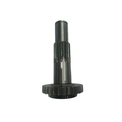
Transmission Shaft If you’re interested in learning more about gear system design or would like to discuss your specific requirements, please don’t hesitate to contact me. I look forward to working with you to design and manufacture the perfect gear system for your application.
References
- Budynas, R. G., & Nisbett, J. K. (2011). Shigley’s mechanical engineering design. McGraw-Hill.
- Dudley, D. W. (1962). Gear handbook. McGraw-Hill.
- Townsend, D. P. (1992). Dudley’s gear handbook. Marcel Dekker.
Yancheng Botu Transmission Machinery Co., Ltd.
As one of the most professional gear manufacturers and suppliers in China, we have world-leading production equipment and strong manufacturing capabilities. Please rest assured to wholesale cheap gear for sale here from our factory. Contact us for more details.
Address: No. 33, Yongxing Road, Economic Development Zone, Jianhu County, Yancheng City, Jiangsu Province
E-mail: 15261979878@163.com
WebSite: https://www.ycbtcdjx.com/
